Gameboy Development Forum
Discussion about software development for the old-school Gameboys, ranging from the "Gray brick" to Gameboy Color
(Launched in 2008)
You are not logged in.
Ads
#1 2018-04-15 06:21:21
- WeaselBomb
- Member
- Registered: 2018-03-06
- Posts: 86
- Website
Gameboy MBC3 capacitor/crystal values?
Hello,
I have made a flash cartridge using an MBC3 chip, and everything works except for the oscillator circuit. I am using a 12.5 pF oscillator and two 15 pF loading capacitors. I am also using a series resistor of 330K ohms. They are arranged similarly to an original cart: trace runs from MBC through resistor, then C1, then through oscillator and back through C2. The circuit worked on my breadboard but not on my pcb. Any suggestions? I can provide more info as needed.
Offline
#2 2018-04-15 17:35:38
- Tauwasser
- Member

- Registered: 2010-10-23
- Posts: 160
Re: Gameboy MBC3 capacitor/crystal values?
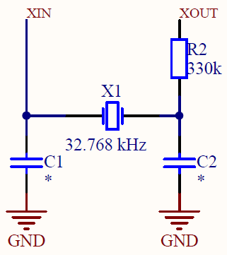
The circuit is not supposed to run through a capacitor. You'd need very fast drivers for that to work, because the caps would act as a high-pass filter. The circuit should look like this:
XIN is pin 19 and XOUT is pin 20 of the MBC3 and you cannot switch them. The resistor is important to hit the right frequency.
cYa,
Tauwasser
Offline
#3 2018-04-15 21:02:30
- WeaselBomb
- Member
- Registered: 2018-03-06
- Posts: 86
- Website
Re: Gameboy MBC3 capacitor/crystal values?
Sorry, my post was badly worded. My circuit is set up like that picture. It seems that I have miscalculated the capacitance values for the oscillator. I am using the equation:
CL = (C1 * C2)/(C1 + C2) + CS
CL = crystal load capacitance
C1, C2 = cap 1 capacitance, cap 2 capacitance
CS = stray capacitance
Using a 12.5 pF crystal, I estimated CS to be 5 pF, which is just a blind guess. This resulted in C1, C2 = 15 pF, but I am not getting any oscillations. Could it be an issue with my trace size? My trace width is .17 mm.
Offline
#4 2018-04-17 18:03:05
- Tauwasser
- Member

- Registered: 2010-10-23
- Posts: 160
Re: Gameboy MBC3 capacitor/crystal values?
Honestly, it could be bad luck, but I would expect some oscillation in that case. I usually just go with 22pF for MHz range oscillators and never noticed any issue. Personally I find 5 pF stray capacitance a pretty high assumption, but it depends on the PCB, the chip process etc. In general I also find capacitor selection hard and usually try to adhere to device manufacturers' recommendations.
Some farfetched things I can think of is that the MBC3 has a weird pin that is only ever described as #WP (write protect?). It is usually connected to a high-active CS from the backup battery IC. There is also the PHI pin that is connected to the edge connector. I could imagine this somehow influencing the clock circuit, because it is supposedly used for synchronizing the clock registers.
EDIT: How do you actually know the crystal isn't oscillating? You aren't measuring with a regular oscilloscope probe, are you?
Last edited by Tauwasser (2018-04-17 18:09:21)
Offline
#5 2018-04-17 18:44:59
- WeaselBomb
- Member
- Registered: 2018-03-06
- Posts: 86
- Website
Re: Gameboy MBC3 capacitor/crystal values?
I assumed the MBC wasn't malfunctioning, because I could play games just fine, so I just assumed it was an issue with the oscillator.
After soaking the board in alcohol, scrubbing, rinsing, and drying, the oscillator seems to be working great. My guess is that I missed some flux that was interfering somehow? It really surprised me when it started working.
Offline
#6 2018-04-18 18:16:52
- Tauwasser
- Member

- Registered: 2010-10-23
- Posts: 160
Re: Gameboy MBC3 capacitor/crystal values?
Ah, condensation can affect the clock crystal and cause it to stop swinging mechanically. Nintendo even advises that this might happen:
3.5.2 Condensation
MBC3 uses a crystal oscillator for its clock counter operation, and condensation on the oscillator may halt
its oscillation, preventing the clocks from counting up. Once the condensation disappears, the clocks will
resume counting up from where they stopped. However, please ensure that the counter stoppage does not
result in a loss of program control.
Offline