Timer Obscure Behaviour
Timer Global Circuit
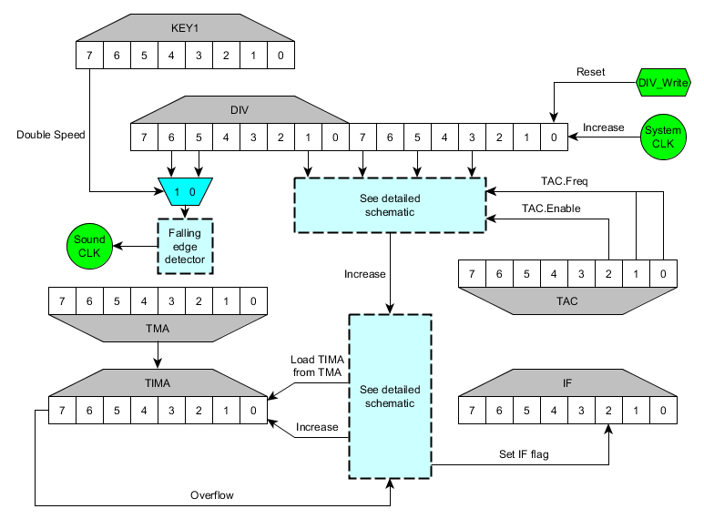
Relation between Timer and Divider register
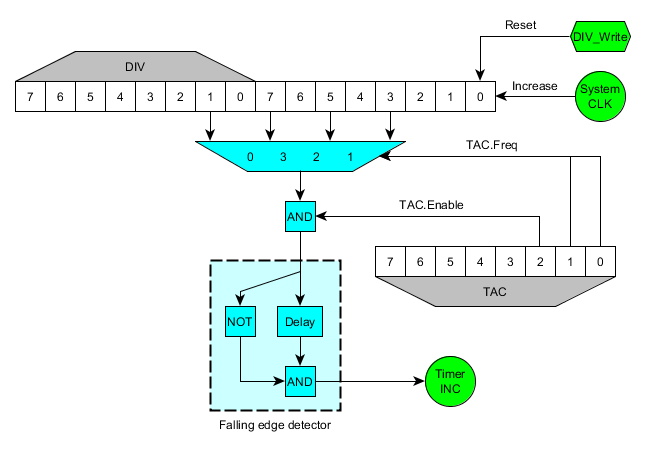
This is a schematic of the circuit involving TAC and DIV:
Notice how the values that are connected to the inputs of the multiplexer are the values of those bits, not the carry of those bits. This is the reason of a few things:
- When writing to DIV, the whole counter is reseted, so the timer is also affected.
- When writing to DIV, if the current output is '1' and timer is enabled, as the new value after reseting DIV will be '0', the falling edge detector will detect a falling edge and TIMA will increase.
- When writing to TAC, if the previously selected multiplexer input was '1' and the new input is '0', TIMA will increase too. This doesn't happen when the timer is disabled, but it also happens when disabling the timer (the same effect as writing to DIV). The following code explains the behaviour in DMG and MGB.
clocks_array[4] = {1024, 16, 64, 256}

old_clocks = clocks_array[old_TAC&3]
new_clocks = clocks_array[new_TAC&3]

old_enable = old_TAC & BIT(2)
new_enable = new_TAC & BIT(2)

sys_clocks = 16 bit system counter

IF old_enable == 0 THEN
    glitch = 0 (*)
ELSE
    IF new_enable == 0 THEN
        glitch = (sys_clocks & (old_clocks/2)) != 0
    ELSE
        glitch = ((sys_clocks & (old_clocks/2)) != 0) && ((sys_clocks & (new_clocks/2)) == 0)
    END IF
END IF
The sentence marked with a (*) has a different behaviour in GBC (AGB and AGS seem to have strange behaviour even in the other statements). When enabling the timer and maintaining the same frequency it doesn't glitch. When disabling the timer it doesn't glitch either. When another change of value happens (so timer is enabled after the write), the behaviour depends on a race condition, so it cannot be predicted for every device.
Timer Overflow Behaviour
When TIMA overflows, the value from TMA is loaded and IF timer flag is set to 1, but this doesn't happen immediately. Timer interrupt is delayed 1 cycle (4 clocks) from the TIMA overflow. The TMA reload to TIMA is also delayed. For one cycle, after overflowing TIMA, the value in TIMA is 00h, not TMA. This happens only when an overflow happens, not when the upper bit goes from 1 to 0, it can't be done manually writing to TIMA, the timer has to increment itself.
For example (SYS is the system internal counter divided by 4 for easier understanding, each increment of the graph is 1 cycle, not 1 clock):
Timer overflows:

              [A] [B]
SYS  FD FE FF |00| 01 02 03
TIMA FF FF FF |00| 23 23 23
TMA  23 23 23 |23| 23 23 23
IF   E0 E0 E0 |E0| E4 E4 E4

Timer doesn't overflow:

              [C]
SYS  FD FE FF 00 01 02 03
TIMA 45 45 45 46 46 46 46
TMA  23 23 23 23 23 23 23
IF   E0 E0 E0 E0 E0 E0 E0
- During the strange cycle [A] you can prevent the IF flag from being set and prevent the TIMA from being reloaded from TMA by writing a value to TIMA. That new value will be the one that stays in the TIMA register after the instruction. Writing to DIV, TAC or other registers won't prevent the IF flag from being set or TIMA from being reloaded.
- If you write to TIMA during the cycle that TMA is being loaded to it [B], the write will be ignored and TMA value will be written to TIMA instead.
- If TMA is written the same cycle it is loaded to TIMA [B], TIMA is also loaded with that value.
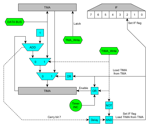
- This is a guessed schematic to explain the priorities with registers TIMA and TMA:
TMA is a latch. As soon as it is written, the output shows that value. That explains that when TMA is written and TIMA is being incremented, the value written to TMA is also written to TIMA. It doesn't affect the IF flag, though.


